Making Adafruit Pixel Goggles
Let me start with the motivation for this project. On one hand, I had never really created a solution with a micro controller, and on the other I wanted to create a cool Halloween costume. The rest of my family was getting dressed up in steampunk outfits, and for a change, I wanted to add something to the mix. But, to do this, I was going to have to learn how to program this micro controller, solder, and how to get the code on the NeoPixel. I know that some people would laugh and say that this would be an easy project, but when you have never worked on this before, it is a completely different case.
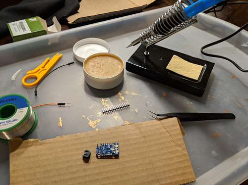
Enough back story, time to walk through the build process. First, there are a the items that you will need to build out the entire unit. You will need a soldering iron. That is if you want to make it permanent. Otherwise, you will need a pair of goggles, 2 Adafruit NeoPixels, and an Adafruit Trinket. You also need a portable battery and a hookup to provide the power to the NeoPixel rings. I can break down the list and links, but they may go bad after a while. There is also a kit
- Goggles
- Adafruit NeoPixel Ring
- Adafruit NeoPixel Trinket
There are instructions on the Adafruit website, but to be honest I found them a bit difficult to follow. There was some difficulty in understanding the instructions and what they were implying. They did have a very nice diagram that was of more use than the rest of the instructions. And, given everything, that is all you really need as far as laying out the wires.
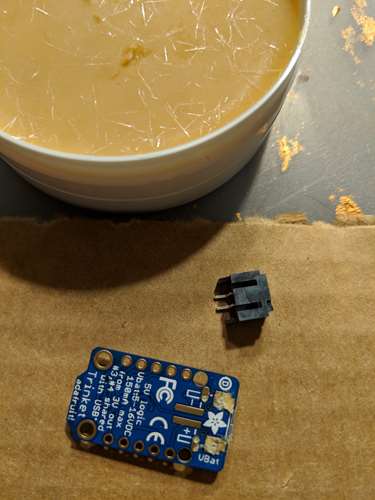
First action is to solder on the JST-PH 2-Pin SMT Right Angle Connector to the Trinket. The USB power to the Trinket is not enough to power the NeoPixel Rings. As a result, you really need to hook up the connector so that you can provide a 5v power supply to the Trinket. Don’t make the same mistake that I did and hook up a 9v battery. This will be to much power, and the rings will only work sporadically. There is a technical reason for this, but I don’t remember electrical theory to explain it. I know enough to know that it will not work right.
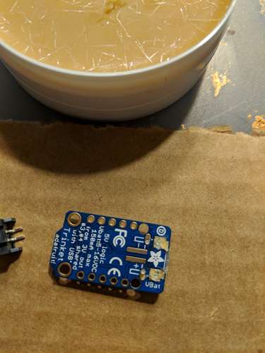
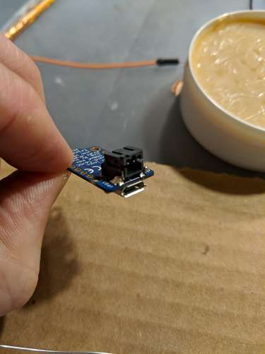
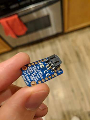
Once you have the power supply soldered onto the back of the board, then the fun really begins. The power supply connectors are on the back and this is where you have to connect the adapter. There is a way to test the power supply, and that is to load the blink code onto the Trinket. I will make sure that is in my code sample. At this point, you should have a trinket that has a power supply hooked up to it, and the ability to push code to the Trinket.
That is one thing that I should have touched on. It was a huge pain to get the code to push to the Trinket when I first started working with it. I ended up have to install a very specific version of the Arduino development plaftorm, version 1.8.5, in order to get the libraries to work. In retrospect, I would have seen if I could have found a Trinket M0 board. That board is supposed to support python, and has more options when it comes to the IDE. However, as of this writing, I had to use a specific version of the Arduino IDE, but I was able to get all of it working. Just remember, that sometimes compiling the software first before pushing the button to sync makes it easier to get it all done in time.
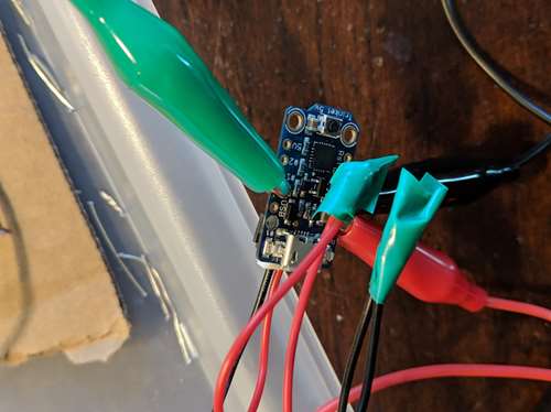
The next thing to do was to hook up all the wires and see if it would work. Seeing as this was my first time working on the Trinket and with the NeoPixels I was not sure if I was going to get the wiring done correctly. To ensure that I was doing it right, I decided to use wires with (sic) roach clips to validate the circuit that I was going to make. At first I was intimidated by the circuit, and thought I was going to mess something up. In retrospect, it was pretty simple.
First, lets talk about getting power to the rings. On the one side of the Trinket you have 2 connections. One connection is for outgoing power and the other is ground. There may be a technical reason for the name ground, but the simple part of it is that you need to create a complete circuit. This means the power goes from the power output on the board and goes to the power input on the NeoPixel. Then, then ground needs to come back to the board to complete the circuit. To add another ring to the mix, you take the second power connection from the NeoPixel and connect it to one of the power points on the other NeoPixel ring. Then hook up one of the ground connections to the second ground connection on the first ring. Bam! Power to both.
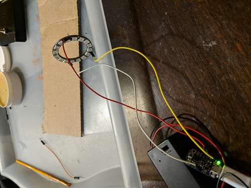
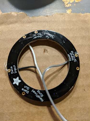
That is great and all, but you need to get the data to the rings. For this, the rings have a ‘data in’ and a ‘data out’ port. Unlike the power connection, this does not have to complete an entire circuit. You just select the outbound pin you want to use from the Trinket and connect it to the data in slot on the first board, then you connect the data out connection from that board to the data in on the second board. That is all. I thought there was more to it. There is not.
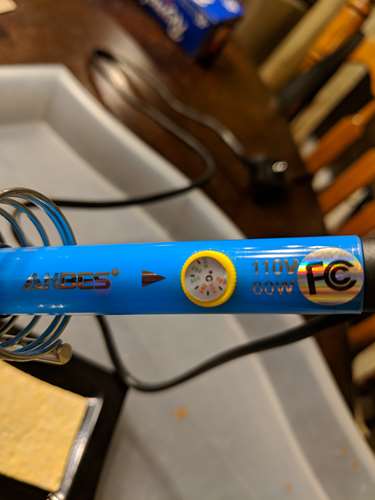
I will be the first to admit that I did a horrible job at soldering. It was my first time, and I had the temperature set to low, and then I had the wrong power level, so when I thought it was wrong, it turned out to be right, and I redid the entire thing. Don’t be me. Make sure you check the power 6 times and test after every solder. Unless, you are like a friend of mine. He had a job doing soldering, and he is a godlike at it.
 The last part is the code. Ah, this is much more fun, and I think I might come back and revisit this later. Needless to say, the samples are here. I am a big fan of github and bitbucket for storing and sharing projects. That is a song and dance for a different day.